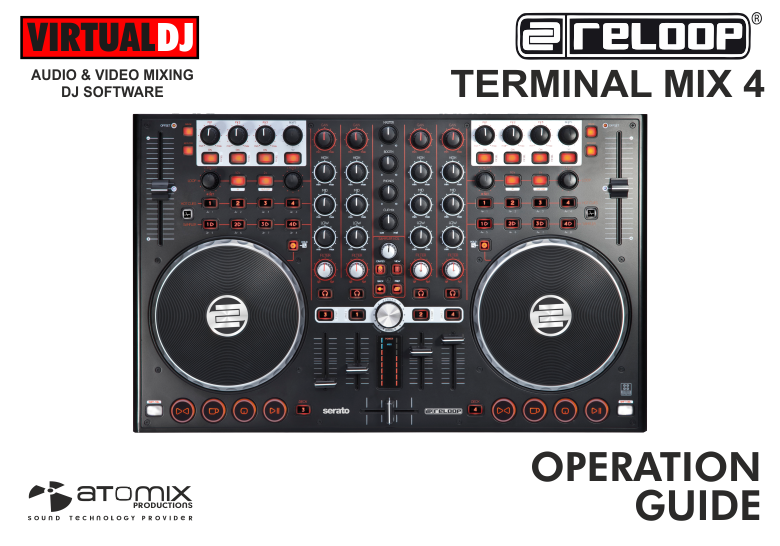
RELOOP TERMINAL MIX 4
SETUP
Firmware & Drivers
Firmware: Update the firmware of the unit to the latest version from http://www.reloop.com/reloop-terminal-mix-4
Drivers (for Windows only): Install the latest Reloop ASIO drivers from http://www.reloop.com/reloop-terminal-mix-4
No drivers are required for Mac OSX computers
VirtualDJ Setup
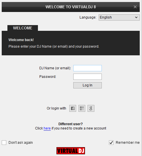
Once VirtualDJ 8 is launched, a Login Window will appear. Login with your virtualdj.com account.
A Pro Infinity or a Subscription License is required to fully use the Reloop Terminal Mix 4. Without any of the above Licenses, the controller will operate for 10 minutes each time you restart VirtualDJ.
http://www.virtualdj.com/buy/index.html
Click on the Use Soundcard button, if your speakers are connected to the Master Output of the unit at the rear panel and your Headphones to the front socket.
Click to OK.
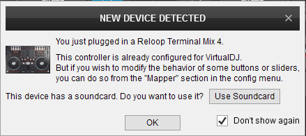
The unit is now ready to operate.
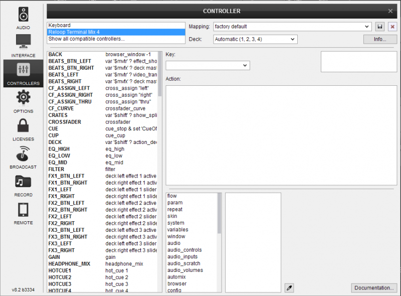
MIDI Operation
Find more details at http://www.virtualdj.com/wiki/VDJ8script.html
AUDIO Setup
Alternative Audio setups can be applied in the same window. See Advanced Setup
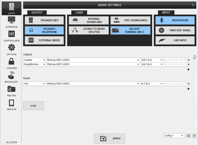
For further software settings please refer to the User Guides of VirtualDJ 8.
http://www.virtualdj.com/manuals/virtualdj8/index.html
LAYOUT
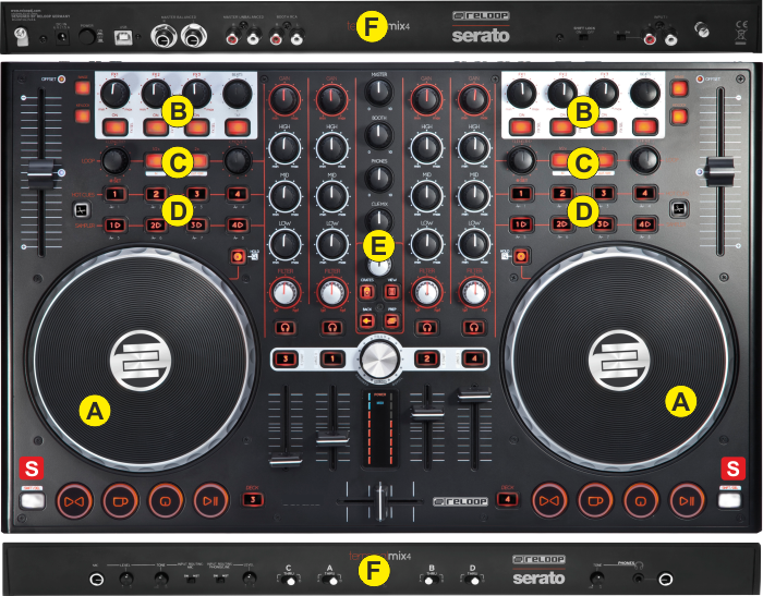
S. SHIFT. Press and hold this button to access secondary functions of other controls on the Terminal Mix 4 The SHIFT button can operate as a toggle or a momentary one depending on the SHIFT switcher ().
The functionality of each button and knob per section (as shown in the image below) will be explained in detail in the next chapters
A. Deck Controls
B. Effect Controls
C. Loop Controls
D. Hotcues & Sampler
E. Mixer & Browser
F. Front & Rear
DECK CONTROLS
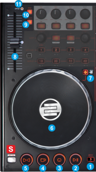
- DECK SELECT. Use the left button (DECK3) to select deck 1 or deck 3 as the controlled deck of the left side, and the right button (DECK4) to select deck 2 or deck 4 as the controlled deck of the right side.
- PLAY/PAUSE. Plays / Pauses the track. Press SHIFT down and then press this button to play the track in stutter.
- CUE. When the Deck is paused, you can set a temporary Cue Point by moving the Platter to place the Audio Pointer at the desired location and then pressing the Cue Button.
During playback, you can press the Cue Button to return the track to this Cue Point. (If you did not set a Cue Point, then it will return to the beginning of the track.). If the Deck is paused, you can press and hold the Cue Button to play the track from the Temporary Cue Point. Releasing the Cue Button will return the track to the temporary Cue Point and pause it.
To continue playback without returning to the Temporary Cue Point, press and hold the Cue Button, then press and hold the Play Button, and then release both buttons.
When the track is paused, hold SHIFT down and then press this button to cycle through the available Cue points. - CUP. If this button is pressed and held down, it sets a temporary Cue Point at the current position if the track is paused, or will jump to the previously stored Cue point if the track is playing. When the button is released, the track will continue to play from that point.
- SYNC. Press this button to automatically match the corresponding Deck's tempo with the Master Deck’s tempo and phase.
Hold SHIFT down and then press this button to manually set a deck as Master Deck. When a Deck is set as MAster Deck, all other Decks will sync to this Deck if SYNC is pressed on those decks. - JOGWHEEL. Touch sensitive platter for scratching (vinyl mode), bending (CD Mode) or fast Seek, depending on the selected mode.
In Scratch mode, use the jogwheel to scratch and the outer ring to bend (temporary slowdown/speed-up tempo)
In Bend mode, use the jogwheel to temporary slowdown/speed-up the tempo of the track.
In Seek mode, use the jogwheel to fast seek through the track. - JOG MODE. Use this button to toggle between the Scratch (Vinyl) and Bend (CD) mode. Press and keep this button down to set the Jogwheel in Seek mode (as long as the buttons is pressed)
- PITCH. Controls the track's playback tempo. The blue led indicates that the pitch fader of the unit is on zero (center) position
- KEYLOCK. Press this button to enable/disable Master Tempo (Key Lock) on the deck.
Hold SHIFT down and then press this button to enable/disable Pitch Lock. When Pitch Lock is enabled the led of this button will blink and all the software pitch faders will move to the same amount if any of the hardware pitch faders are moved. - RANGE. Press this button to select the next available pitch range. The pitch range applies to all VirtualDJ decks (global setting).
Hold SHIFT down and then press this button to smoothly reset the tempo of the track to its original value. - OFFSET. This Led will be turned On if the hardware and the software values of the pitch (tempo) don’t match. This may happen when decks are swapped (left and right) or the SYNC is pressed. The hardware pitch slider will not alter the tempo of the track until it meets the value of the software tempo.
Effect Controls
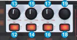 This section offers control of 3 Effect slots per deck, Beatgrid adjustments, Master video Effects and Video Transition controls.
- FX1 ON. Press this button to enable/disable the selected effect of FX Slot 1. Hold SHIFT down and then press this button, to select the next available effect for FX Slot 1.
- FX1 knob. Controls the 1st parameter of the selected effect of FX Slot 1. Hold SHIFT down and use this knob to control the 2nd parameter of the selected effect of FX Slot 1.
- FX2 ON. Press this button to enable/disable the selected effect of FX Slot 2. Hold SHIFT down and then press this button, to select the next available effect for FX Slot 2.
- FX2 knob. Controls the 1st parameter of the selected effect of FX Slot 2. Hold SHIFT down and use this knob to control the 2nd parameter of the selected effect of FX Slot 2.
- FX3 ON. Press this button to enable/disable the selected effect of FX Slot 3. Hold SHIFT down and then press this button, to select the next available effect for FX Slot 3.
- FX3 knob. Controls the 1st parameter of the selected effect of FX Slot 3. Hold SHIFT down and use this knob to control the 2nd parameter of the selected effect of FX Slot 3.
- TAP. Press this button (for at least 4 times while track is playing) to manually tap the tempo of the track
Hold SHIFT down and then press this button to set the TAP button and the BEATS ENC (19) to Video mode (led will be On)
The Video mode is side/deck dependent (can be enabled/disabled on either side separately).
In Video mode, use the button on the left side to trigger the selected Video Transition, and the button on the right side to trigger the selected Video Effect on Master. - BEATS ENC. Use the encoder to move the track forward or backwards by 1 beat. Hold SHIFT down and then use this encoder to move the CBG of the track by 1 beat forward or backwards.
If the Video mode is enabled, use the encoder on the left side to select a Video Transition and the encoder on the right side to select a Video Effect on Master. Hold SHIFT down and then use the same encoders to adjust the 1st parameter (if available) of the selected Video Transition or Video Effect on Master respectively
LOOP CONTROLS
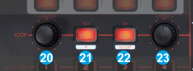
- LOOP SIZE. Turn the encoder anti-clockwise to half the size of the loop and clockwise to double it.
Push the encoder to trigger a loop of the selected size.
Hold SHIFT down and then push the encoder to enable/disable the Loop Roll mode. When the Loop Roll mode is enabled the triggered loops will have temporary effect and when turned off (disabled) the track will return to the position it would have been if the loop was never triggered. - LOOPIN. Use this button to set a Loop In (Entry) point for manual loop.
- LOOPOUT. Use this button to set a Loop Out (Exit) point and complete a manual loop. Use the same button to exit the Loop if triggered.
- LOOP MOVE. When a Loop is enabled, turn the encoder anti-clockwise to move the triggered loop forward or backwards by the amount of beats equal to the triggered loop. Hold SHIFT and then use the same encoder to move the triggered loop forward or backwards by 4 beats.
Push the encoder to trigger a loop of the selected size
Hold SHIFT down and then push the encoder to enable/disable the Smart Loop. When Smart Loop is enabled, a manual loop (using the LOOPIN, LOOPOUT buttons) will snap to the nearest size in beats, offering seamless looping.
HOTCUES & SAMPLER
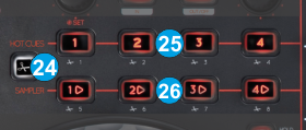 This section offers HotCues and Sampler Control and 2 different banks for each one.
- BANK Use this button to choose the 1st or the 2nd bank for both HotCues and Sampler. When the led of this button is turned on, the HotCues and Sampler buttons will offer control of the 2nd bank.
- HOTCUES 1-4/(5-8). Each one of the 4 HotCue buttons assigns a Hot Cue Point 1 to 4 (or 5 to 8 if the 2nd bank is selected) or returns the track to that Hot Cue Point.
When a Hot Cue Button is unlit, you can assign a Hot Cue Point by pressing it at the desired point in your track. Once it is assigned, the Hot Cue Button will light up red.
Hold SHIFT and then press a button to delete its assigned Hot Cue Point. Red leds will blink if a HotCue point exists. - SAMPLES 1-4/(5-8) Each one of the 4 Sampler buttons triggers a sample from the selected Sampler Bank of VirtualDJ8. The buttons will control samples 1 to 4 (or 5 to 8 if the 2nd bank is selected).
If a bank has less than 9 samples, both sides of the Terminal Mix 4 will control the same samples. If a bank has more than 8 samples, the left side of the Terminal Mix 4 will control samples 1 to 8 and the right side samples 9 to 16.
The Leds of the Sampler buttons will be turned on if a sampler slot is available (loaded) and will blink is triggered.
Press the buttons to trigger a sample. Depending on the selected trigger mode, use SHIFT and the same pads to stop the sample.
MIXER & BROWSER
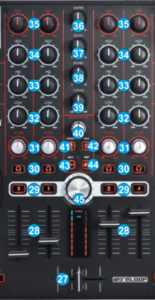
- CROSSFADER. Blends audio between the channels assigned to the left and right side of the crossfader.
- VOLUME. Adjust the Volume of each channel.
- LOAD. Press these buttons to load the selected track from the Browser to decks 1 to 4. The LED of the button will be on if the deck is loaded. Hold the same button for more than 2 seconds to unload the same deck.
Hold SHIFT down and then press one of these buttons to enable the Fader Start on a deck. - PFL. Press these buttons to send one (or more) channel to the Headphones Output channel.
- FILTER. Use this knob to apply a High/Low Pass Filter to the deck. In middle position no filter is applied.
- EQ LOW. Adjust the Low (Bass) frequencies for each mixer channel.
- EQ MID. Adjust the Mid frequencies for each mixer channel.
- EQ HIGH. Adjust the High (Treble) frequencies for each mixer channel.
- GAIN. Adjust the Gain of each mixer channel.
- MASTER VOLUME. Adjust the level of the Master Output of the TM4 Audio Interface. Hardware operation - movement not visible on the VirtualDJ GUI
- BOOTH VOLUME. Adjust the level of the Booth Output of the TM4 Audio Interface. Hardware operation – movement not visible on the VirtualDJ GUI.
- HEAPHONES LEVEL. Adjust the Volume of the Headphones Output of the TM4 Audio Interface. Hardware operation – movement not visible on the VirtualDJ GUI.
- HEADPHONES MIXING. Adjust how the Channels and the Master Output blend at the Headphones Channel.
- SAMPLER VOLUME. Adjust the Master Output Volume of the VirtualDJ Sampler
- CRATES. Cycles through the views of the Sideview (Automix, Sidelist, Sampler, Karaoke and Clones). Hold SHIFT down and then press this button to show/hide the Sideview.
- VIEW Cycles through the available Center Mixer panels of the default VirtualDJ GUI (Mixer, Video, Scratch and Master). Hold SHIFT down and then press this button to show Browser Zoom view.
- BACK. Set focus to the previous Browser Window (Folders List, Songs List and Sideview).
- PREPARE. Add the selected track to the Automix List. Hold SHIFT down and then press this button to add the selected track to the Sidelist.
- BROWSE ENC. Scroll through files of folders. Push the encoder to enter the Songs List (if focus is on the folders list) or load the selected track to the first available deck. Hold SHIFT down and then push the encoder to set focus to the Folders list or open/close the subfolders if focus is on the Folders list already.
FRONT & REAR PANELS

- MIC INPUT. Connect your 1/8” Microphone to this Input.
- MIC LEVEL/TONE. Adjust the signal Level and the Tone of the Microphone Input. Hardware operations (not visible on the VirtualDJ GUI), however the Microphone Input can be routed into the software (see Advanced Setup)
- INPUT ROUTING MIC. Select with this switcher if the Microphone Input will be directly routed to the Master Output of the TM4 (MST position) or to the software mix (SW position).
- INPUT ROUTING PHONO/LINE. Select with this switcher if the Phone/Line Input (connection at the rear side) will be directly routed to the Master Output of the TM4 (MST position) or to the software mix (SW position).
- LINE LEVEL. Adjust the signal Level and the Tone of the Phone/Line Input. Hardware operations (not visible on the VirtualDJ GUI), however the Line/Phono Input can be routed into the software (see Advanced Setup)
- CF ASSIGNS. Define which mixer channels (decks) will be assigned as left (A position) or right (B position) side of the crossfader. If in a channel is at THRU position, the channel will be heard in Master Output regardless of the Crossfader position.
- CF CURVE. Define how the crossfader will blend the mixer channels.(from Smooth to Cut/Scratch curve)
- HEADPHONES TONE. Adjust the tone of the Headphones Output Channel. Hardware Operation, not visible on the GUI of VirtualDJ.
- HEADPHONES PHONES INPUT. Connect a pair of Headphones to this socket (1/4” or 1/8”). The Volume of this Output is controlled by the knob at the top panel

- POWER: The unit can be powered only via the USB connection, however a Power connection (using a proper AC/DC adaptor) is required to route the analogue inputs directly to the Master Output (stand-alone operation). While the power is switched off, plug the cable into TM4 first, and then plug the cable into a power outlet. Use the Power Switch to turn the TM4 on and off. Turn on the TM4 after all input devices have been connected and before you turn on amplifiers. Turn off amplifiers before you turn off TM4.
- USB. This USB connection sends and receives audio and control information from a connected computer.
- MASTER OUTPUT BALANCED (TRS): Connect this low-impedance TRS output to a PA system or powered monitors. The level of this output is controlled with the Master knob on the top panel.
- MASTER OUTPUT UNBALANCED (RCA): Use standard RCA cables to connect this output to a speaker or amplifier system. The level of this output is controlled by the Master knob on the top panel.
- BOOTH OUTPUT (RCA): Use standard RCA cables to connect this output to a booth monitoring system. The level of this output is controlled by the Booth knob on the top panel.
- SHIFT LOCK. Choose if the SHIFT buttons on the top of the panel will behave temporary (while pressed) or toggle (on/off)
- LINE/PHONO. Select the appropriate position, depending on the analogue media source connected to the Input socket.
- LINE INPUT. Connect your audio sources to this input.
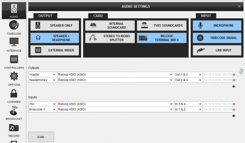
Advanced Setup
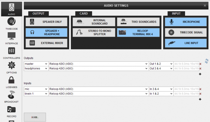
The Terminal Mix 4 offers 2 stereo Inputs. A LINEIN at the rear side (Input Channels 1 and 2) and a Microphone Input at the front (Input channels 3 and 4). Each one of the Inputs can be routed through the Master Output directly (front switchers to MST position) or through VirtualDJ (front switchers to SW position). A Level knob for each Input is offered to adjust its Input Volume.
Recording & Broadcasting
The unit offers the ability to record the Master Output along with the Microphone and LINE Inputs directly from VirtualDJ record button (in the MASTER center panel).
In this case, both the Microphone and LINE Inputs need to be in SW Input mode.
The Microphone Input is already part of the pre-defined audio configuration, therefore only a Line In line needs to be manually added to the audio configuration, as per the following image.
Note. If the Line or the Microphone Inputs are not required to be recorded, it is advised not to route the Microphone through the software, as an additional latency will be applied.
Timecodes (DVS)
Even though the Terminal Mix 4 is not designed to support Timecoded CDs and Vinyls (DVS), the unit is capable to offer Timecode setups. In theory only a single Timecode device can be used (connection to the LINE Input), however a second Timecoded device can be also connected to the MIC Input (and adjust the Level of its signal).
The following audio configuration is showing an audio configuration with a single Timecode input.